Warning: When handling the SNMPWEBCARD, follow standard ESD (electrostatic discharge) precautions to avoid damaging the card. For your safety, you should also read the documentation that came with your UPS system or PDU to familiarize yourself with precautions against electric shock.
 An SNMPWEBCARD allows users to operate any compatible Eaton UPS System or network-enabled PDU as a managed device on the network, accessible via Web browser, Network Management Station or telnet/SSH. This article refers to installing the card in a UPS system, but the same instructions apply to installing the card in a compatible PDU.
Confirm Package Contents
Your package should include the accessory card in an anti-static bag, a configuration cable (73-1025) and several faceplates. If anything is missing, contact your supplier immediately. Additional documentation and Management Information Base (MIB) files for use with Network Management Systems (not otherwise required) can be found by going to tripplite.eaton.com/support/index and typing
SNMPWEBCARDin the search field.Note for Network Management System Users Only: Two MIB files - Tripplite.mib and RFC1628.mib - must be loaded on each Network Management Station that will monitor the UPS system via SNMP. The files can be found by going to tripplite.eaton.com/support/index and typing
SNMPWEBCARDin the search field.Install UPS
Install your UPS system and turn it on before installing the SNMPWEBCARD. Ensure the accessory card slot is accessible.
Locate MAC Address
The 12-digit MAC address (000667xxxxxx) is printed in two locations: a label attached to the underside of the card and a duplicate label inside the box. Attach the duplicate label to the UPS system or keep it in a secure location for easy reference.
Address Assignment
If your network's DHCP server will assign a dynamic IP address to the SNMPWEBCARD automatically, proceed to Dynamic IP Address Assignment. If you will assign a static IP address to the SNMPWEBCARD manually, proceed to Static IP Address Assignment/Terminal Menu Configuration.
If you are uncertain which method to use, contact your network administrator for assistance before continuing the installation process.
Where can you find more advice if you need it?
As you build, expand or reassess your IT infrastructure, don't shortchange your power management requirements. It's an area for potentially significant cost savings, and it's of extreme importance in ensuring uptime and system availability. Installing power management functionality to your UPS system can be a complex task, especially since your organization may require different UPS systems for different applications.
Eaton provides various online resources to help you install and manage UPS power management software:
- Detailed PowerAlert® Network Management System features at https://tripplite.eaton.com/products/power-alert-network-management-system
- PowerAlert software downloads at https://tripplite.eaton.com/products/power-alert
- Our Chicago-based support team at tripplite.eaton.com/support/index
Insert SNMPWEBCARD into Accessory Slot
Use a screwdriver to remove the accessory slot cover from the UPS. While the UPS is turned on, align the SNMPWEBCARD with the guides in the accessory slot and push the card into the slot until the ports are nearly even with the rear surface of the UPS.
Connect SNMPWEBCARD to Network
Connect a standard Ethernet patch cable to the RJ45 Ethernet port on the card.
Note: This port does not support PoE (Power over Ethernet) applications. The card will attempt to obtain an IP address via DHCP. This may take as long as several minutes, depending on your network environment.
Discover IP Address
Contact your network administrator to determine which IP address has been assigned to the card by the DHCP server. The card can be identified on the DHCP server by referring to its MAC address (see Locate MAC Address ). You may wish to request a long-term lease period for the IP address, depending on your application. After you have discovered the IP address, proceed to Test and Configure.
Note: The DHCP addresss is also displayed during boot-up when connected to a computer through the configuration cable and a terminal emulation program.
Note: As of firmware version 12.06.006X, the SNMPWEBCARD supports both IPv4 and IPv6. It is set up by default to receive a DHCP address for IPv4, IPv6 or both. Receiving both addresses allows connection to the card by either IPv4 or IPv6 address.
Where can you find more advice if you need it?
As you build, expand or reassess your IT infrastructure, don't shortchange your power management requirements. It's an area for potentially significant cost savings, and it's of extreme importance in ensuring uptime and system availability. Installing power management functionality to your UPS system can be a complex task, especially since your organization may require different UPS systems for different applications.
Eaton provides various online resources to help you install and manage UPS power management software:
- Detailed PowerAlert® Network Management System features at https://tripplite.eaton.com/products/power-alert-network-management-system
- PowerAlert software downloads at https://tripplite.eaton.com/products/power-alert
- Our Chicago-based support team at tripplite.eaton.com/support/index
Determine IP Information
The SNMPWEBCARD can support a single static IPv4 address (requires setting the IP address, subnet mask and gateway) and/or a single IPv6 static address. In addition, the SNMPWEBCARD can support a single static IPv4 or an IPv6 DNS address that is required to be entered.
-
Configure Terminal Emulation Program
Open a VT100-compatible terminal emulation program (such as the HyperTerminal program bundled with Microsoft® Windows®) on a computer with an available DB9 serial port. (Note: If a DB9 port is not available, a Serial to USB adapter (sold separately) can be used for configuration.) Set the terminal emulation program to use the COM port A that corresponds to the DB9 serial port. Specify the parameters B required to communicate with the SNMPWEBCARD terminal interface.
If the terminal emulation program supports multiple emulation modes, you may also need to specify VT100 emulation C.
Bits per second 9600 Data bits 8 Parity None Stop bits 1 Flow control None A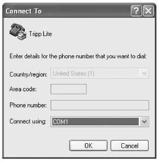 B
B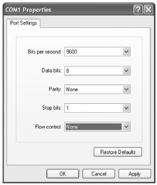 C
C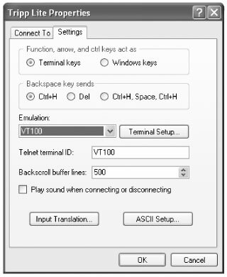
-
Connect SNMPWEBCARD to Computer
Before inserting the card into the UPS, use the configuration cable (part number 73-1025) included with the card to connect the card to the computer. The circular connector A at one end of the cable attaches to the 8-pin mini-DIN serial port B on the card (align the connector carefully to avoid damaging the pins). The DB9 connector C at the other end of the cable connects to the computer's serial port D.

-
Insert SNMPWEBCARD into Accessory Slot
Use a screwdriver to remove the accessory slot cover from the UPS. While the UPS is turned on, align the SNMPWEBCARD with the guides in the accessory slot and push the card into the slot until the ports are nearly even with the rear surface of the UPS.
-
Configure SNMPWEBCARD in Terminal Mode
Within 10-15 seconds, a menu will appear and the boot process will pause for 5 seconds. Press any key within the five second pause to enter Configuration Mode. A prompt will appear asking to (A)ccept settings or (M)odify changes. Press 'M' to modify changes and then login with the default root password
TrippLite(case sensitive). Follow the prompts to make changes.Notes:
-
If a key is not pressed within the five second pause, the boot process will continue. To make changes through the terminal program after this, a reboot is required. A reboot can be accomplished in three ways:
- Pull the SNMPWEBCARD out of the device, and then reinsert it.
- Using a small paper clip, press the reset button through the small hole on the face plate (below the RJ45 network port).
- During the boot process, press any key. This will prompt for a login name and password. Enter the default username
localadmin, the default passwordlocaladmin, and then typereboot. This will restart the card.
-
If you have the terminal program running and do not see the power ON banner, remove the card and reinsert it, or push the reset button.
Welcome to Tripp Lite PowerAlert built on Mar 12 2012 15:06:25
BSP version 012.006.060.000.0075 built on Mar 12 2012 13:41:22
PLATFORM: trippliteSnmpCard9210_H_16_32 16M/32M [Mar 12 2012 13:41:22]
------------------------------------------------------------------------
NETWORK INTERFACE PARAMETERS:
FQDN poweralert-061033462177
The board will obtain IPv4 configuration parameters from the network.
DHCPv6 is enabled on LAN
DNS server is 10.0.0.8
Time is supplied by RTC
Time zone is set to -6:00 from GMT, DST Enabled
SERVICES:
FTP     is  enabled on port 21
HTTP    is  enabled on port 80
HTTPS   is  enabled on port 443
SSH     is  enabled on port 22
SSH     is  enabled on port 2112
TELNET  is  enabled on port 23
TELNET  is  enabled on port 5214
SNMP    is  enabled on port 161
SYSLOG  is  disabled
HARDWARE PARAMETERS:
Serial channels will use a baud rate of 9600
RTC date and time in GMT: 03/13/2012 18:19:51
This board's serial number is
This board's Ethernet MAC Address is 00:06:67:22:3E:B1
After board is reset, start-up code will wait 5 seconds
------------------------------------------------------------------------
Press any key in 5 seconds to change these settings.
Press A to Accept the settings, or M to Modify? m
Enter the root password: *********
3-5-1 NETWORK SETTINGS
Follow the prompts to configure IPv4 and IPv6 address settings. The default terminal mode password is
TrippLite. Sample IP settings are shown; supply your own IP information when configuring your card.Ethernet Interface Settings:
Obtain IPv4 settings automatically using DHCP for Ethernet interface? [Y]
IP address? [10.1.0.165]
Subnet mask? [255.0.0.0]
Gateway address? [10.0.0.1]
Enable DHCPv6 for the Ethernet interface? [Y]
Enable static IPv6 for the Ethernet interface? [N]
IPv6 address? [2001:DB8::1:58:4F43:4849:544C]
Network prefix length? [64]
DNS server? [10.0.0.8]
This card's host name? [poweralert-061033462177]
This card's domain? [tlsoftwaredev.local]
3-5-2 NETWORK SERVICE CONFIGURATION
The following prompts configure the connection methods the SNMPWEBCARD will accept.
Enable SNTP? [Y]     Enable Telnet Menu? [Y]        Port number? [2112]
Enable FTP? [Y]      Port number? [23]              Enable SNMP? [Y]
Port number? [21]    Enable Telnet Programs? [Y]    Port number? [161]
Enable HTTP? [Y]     Port number? [5214]            Enable SNMPv1? [Y]
Port number? [80]    Enable SSH Menu? [Y]           Enable SNMPv2c? [Y]
Enable HTTPS? [Y]    Port number? [22]              Enable SNMPv3? [Y]
Port number? [443]   Enable SSH Programs? [Y]
3-5-3 HARDWARE PARAMETERS
These prompts allow you to modify the hardware parameters of the SNMPWEBCARD, such as time and date settings.
Would you like to update the RTC date/time in GMT? [N]
Time Zone in 30 minute intervals, +/-HH:MM (+ is optional): [-06:00]
Do you wish to configure the advanced settings? [Y/N]
Note: Do not modify advanced settings unless directed by your administrator or Eaton Tech Support.
Time Zone Offsets Supported
Western Hemisphere Eastern Hemisphere Hour Offset Location Hour Offset Location 00:00 Greenwich, England +01:00 Mid Europe/Africa -01:00 SE Greenland +02:00 E Europe, E Central Africa -02:00 Atlantic Ocean +03:00 Moscow, Mid-East, E Africa -03:00 Greenland Time +04:00 NW Caspian Sea -04:00 Atlantic Time +05:00 Ural Mountains, Russia -05:00 Eastern Standard Time +06:00 Almaty (Alma ATA), Russia -06:00 Central Standard Time +07:00 W Mongolia -07:00 Mountain Standard Time +08:00 China -08:00 Pacific Standard Time +09:00 Japan -09:00 Alaska Time +10:00 Eastern Russia, Sydney, Australia -10:00 Hawaii +11:00 Kamchatskiy, E Russia -11:00 Pacific Ocean +/- 12:00 International Date Line 3-5-4 USERS/SNMP
The SNMPWEBCARD allows for twelve users. Users require a username and password of at least eight characters that can be a combination of alphanumeric characters and dashes "—". A user can be defined as an SNMP user or not by defining the SNMP version when setting up the user.
3-5-5 SECURITY SETTINGS
These prompts help define the security levels and access for the SNMPWEBCARD and its users.
Warning: If you choose to edit your Root Password, keep records of the change in a place easily accessible to your network administrators. Eaton CANNOT recover, edit or override changed Root Passwords if they have been lost or forgotten. Eaton CANNOT provide technical support for an SNMPWEBCARD without knowledge of the Root Password. If this occurs, a new SNMPWEBCARD will be needed.
Would you like to update the Root Password? [N]
Do you wish to modify the users? [N]
Do you wish to modify user number 1 "localadmin"? [N]
Do you wish to modify user number 2 "localmanager"? [N]
Do you wish to modify user number 3 "localguest"? [N]
Do you wish to modify user number 4 "public"? [N]
Do you wish to modify user number 5 "tripplite"? [N]
Do you wish to modify user number 6 "cardself"? [N]
Do you wish to modify user number 7 "cardtocard"? [N]
Do you wish to modify user number 8 "-blank-"? [N]
Do you wish to modify user number 9 "-blank-"? [N]
Enter a name for user 8 [-blank-]? [N]
SNMP privilege levels: 0=none, 1=SNMPv1, 2=SNMPv2, 3=SNMPv3
SNMP privilege level for "tripptripp"? [N]
Password for "tripptripp"? **********
Re-enter password for "tripptripp"? **********
Facilities: []: default=rw
Note: Facilities are areas of the program that a user may be given access to, or restricted from.
Available facilities are:
0=default 5=logging 10=actions 1=security 6=device status 11=schedules 2=contacts 7=device controls 12=discovery 3=systemsettings 8=deviceevents 4=systeminfo 9=deviceloads Access options to these facilities are
rw,roornone.For Example:
default=rwindicates the user has read write access to every facility not otherwise specified. This is the level of access userlocaladminhas.default=rw, security=noneindicates that the user has read write access to every facility, but due to the addition of the security facility tag, the user would be restricted from the security settings of the program.Allowed IP address or Address range, v6 or tunneled v4, "::" means any address.
IP address Mask in v6 notation, "::" means any subnet mask.
IPv4 Example:To allow anybody with an address of 10.X.X.X to have access:
Address:::ffff:10.0.0.0
Mask:ffff:ffff:ffff:ffff:ffff:ffff:ff00:0000To allow anybody with an address of 10.20.X.X to have access:
Address:::ffff:10.20.0.0
Mask:ffff:ffff:ffff:ffff:ffff:ffff:ffff:0000To allow anybody with an address of 10.20.1.X to have access:
Address:::ffff:10.20.1.0
Mask:ffff:ffff:ffff:ffff:ffff:ffff:ffff:ff00IPv6 Example:To allow someone from the 3291:2251::0/64 range:
Address:3291:2251::0
Mask:FFFF:FFFF:FFFF:FFFF::0To allow only a small handful of people on the range 4923:2241::3200/120:
Address:4923:2241::3200
Mask:FFFF:FFFF:FFFF:FFFF:FFFF:FFFF:FFFF:FF00This will admit addresses 4923:2241::3200 - 4923:2241::32FF.
3-5-6 RADIUS SERVER CONFIGURATION
These prompts allow the configuration of the only two allocated Radius Servers Entries for the SNMPWEBCARD. Sample Radius configurations are shown; supply your own Radius Server information when configuring your card.
Radius Server Configuration Settings:
Do you wish to modify the radius hosts table? [N]? y
New Domain Name or Address [] RadiusServer.local
New shared secret [] LocalServer
Radius Port [0] 1812
Accounting Port [0] 1813
Server Priority [0] 1
Row Status [1]
	  1) active
	  2) inactive
> 1
Do you wish to alter radius entry 1 "" [N] y
New Domain Name or Address [] RadiusServer.Remote
New shared secret [] RemoteServer
Radius Port [0] 1812
Accounting Port [0] 1813
Server Priority [0] 1
Row Status [2]
	  1) active
	  2) inactive
> 1
3-5-7 AUTHENTICATION METHOD
These prompts determine the method and order of authentication for accessing the SNMPWEBCARD.
Note: Eaton recommends that the "RadiusOnly" authentication method should only be used after the Radius Server had been configured for User Interface accessibility on the SNMPWEBCARD.
Set radius auth order [0]
00) LocalOnly
01) RadiusThenLocal
02) LocalThenRadius
03) RadiusOnly
Set radius accounting order [0]
00) LocalOnly
01) RadiusThenLocal
02) LocalThenRadius
03) RadiusOnly
Erase the server private key passphrase?
Erase the client private key passphrase?
New passphrase for server private key?
Re-enter passphrase for server private key?
New passphrase for client private key?
Re-enter passphrase for client private key?
-
-
Remove Serial Cable
Using one hand to hold the card in place, remove the serial cable. Proceed to Test and Configure.
Where can you find more advice if you need it?
As you build, expand or reassess your IT infrastructure, don't shortchange your power management requirements. It's an area for potentially significant cost savings, and it's of extreme importance in ensuring uptime and system availability. Installing power management functionality to your UPS system can be a complex task, especially since your organization may require different UPS systems for different applications.
Eaton provides various online resources to help you install and manage UPS power management software:
- Detailed PowerAlert® Network Management System features at https://tripplite.eaton.com/products/power-alert-network-management-system
- PowerAlert software downloads at https://tripplite.eaton.com/products/power-alert
- Our Chicago-based support team at tripplite.eaton.com/support/index
-
Test Network Connection
After an IP address has been assigned to the card, try to access it with a Web browser. Open a Web browser on a computer connected to the LAN and enter http:// or https:// followed by the IP address. You should be prompted for a password. The user name is
localadminand the default password islocaladmin. After you enter the user name and password, the PowerAlert Status page will appear in the browser window. For more information about configuration and operation of the managed device, refer to the SNMPWEBCARD User's Guide, located in the support section of the SNMPWEBCARD product web page. -
Changing the Default UPS System Shutdown Settings
During a power failure, the SNMPWEBCARD is pre-configured to shut down the UPS system two minutes after receiving a low battery signal. This allows the UPS system to provide the maximum available runtime to connected equipment.
If you want to change the default setting, follow these instructions and refer to Figures 2-1 and 2-2:
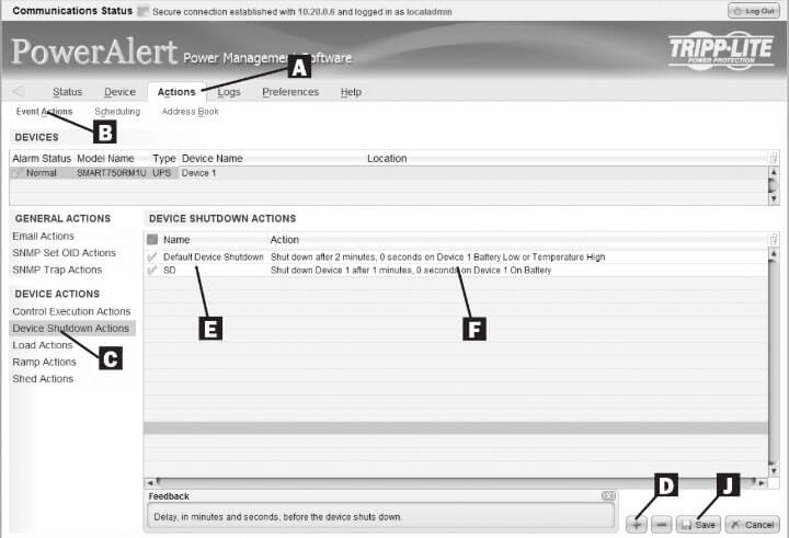 Figure 2-1
1. Use a Web browser to open the PowerAlert console window for your SNMPWEBCARD (see 3.1 Opening the Web Console for instructions).
2. Click the Actions menu A and access the Event Actions submenu B.
3. Select Device Shutdown in the Device Actions C section.
4. Click the + button on the bottom of the screen D to add a new action.
5. In the Name field E, type a name for the new action.
6a. Click the Actions field F to access its submenu.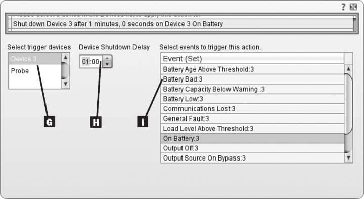 Figure 2-2
6b. Select the device to shut down in the Select Trigger Device section G.
7. Set how long the delay should be before the action will take place H.
8. Select the Event(s) that will trigger the action I.
9. Click the Save button on the bottom of the screen J.Note: Whenever changes are made, the Save button must be pressed to submit the changes before moving off of the page. This also includes deleting fields using the — button. After selecting an item and clicking the — button press the Save button to commit to the change.
4-2-2 Other Default Settings
Setting Default Value Additional Information IP address Obtain from DHCP See Discover IP Address Telnet Access Disabled See Network Service Configuration SSH Access Enabled See Network Service Configuration HTTP Access Enabled See Network Service Configuration HTTPS Access Enabled See Network Service Configuration SNMPv1 Access Enabled — Community —public See Network Service Configuration SNMPv2 Access Enabled — Community —tripplite See Network Service Configuration SNMPv3 Access Enabled
localadmin
localmanager
localguestSee Network Service Configuration Default users and passwords localadmin/localadmin
localmanager/localmanger
localguest/localguestSee Security Settings Radius Disabled See Radius Server Configuration 4-2-3 PowerAlert Software Default Settings
Setting Default Value Additional Information Email Notification Default email action profile setup to trigger 30 seconds after an alarm. Add email destinations in address book. See SNMPWEBCARD User Guide SNMP Trap Notification Default SNMP Trap action profile setup to trigger 30 seconds after an alarm. Add trap destinations to address book. See SNMPWEBCARD User Guide Event Logging Enabled See SNMPWEBCARD User Guide Data Logging Enabled See SNMPWEBCARD User Guide -
SNMPWEBCARD Operating Conditions
Link LED Color Off No Network Connection Flashing Amber 100 Mbps Network Connection Flashing Green 10 Mbps Network Connection Status LED Color Off Card Not Initialized Steady Green Card Initialized and Operational Flashing Amber Error - Card Not Initialized
Where can you find more advice if you need it?
As you build, expand or reassess your IT infrastructure, don't shortchange your power management requirements. It's an area for potentially significant cost savings, and it's of extreme importance in ensuring uptime and system availability. Installing power management functionality to your UPS system can be a complex task, especially since your organization may require different UPS systems for different applications.
Eaton provides various online resources to help you install and manage UPS power management software:
- Detailed PowerAlert® Network Management System features at https://tripplite.eaton.com/products/power-alert-network-management-system
- PowerAlert software downloads at https://tripplite.eaton.com/products/power-alert
- Our Chicago-based support team at tripplite.eaton.com/support/index


